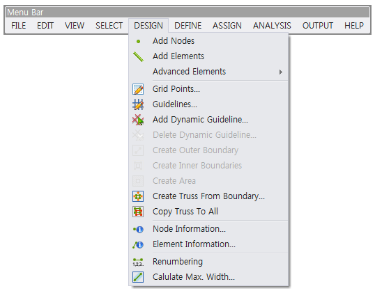
Add Nodes
Finite element nodes for constructing the finite element models of plane solid and truss structures are generated by this function. The generated nodes must be connected to their corresponding finite element(s). This function is used in the Beginning Mode and Modeling Mode – Truss.
Add Elements
A finite element is generated by assigning the coordinates of both end points of the element. More elements are generated by using this function repeatedly. This function is used in the Beginning Mode and Modeling Mode – Truss.
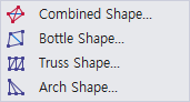
Advanced Elements
Four types of truss element sets shown below are provided to construct a finite element model of truss structure quickly and efficiently. This function is used in the Modeling Mode – Truss and Free Modeling module.
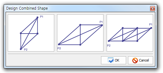
To activate this function, two points, P1 and P2, in the combined shapes shown below must be clicked after selecting one of the combined shapes. The shape of the element set does not change regardless of the clicking order of the two points.
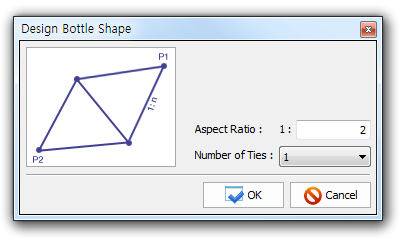
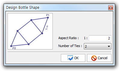
Design Bottle Shape
A bottle-shaped element set is generated by this function. To activate this function, two points, P1 and P2, in the bottle shapes shown below must be clicked after selecting one of the bottle shapes. The aspect ratio to determine the slopes of inclined elements and the number of ties limited to 2 must be assigned.
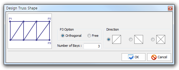
A rectangular-shaped element set is generated by this function. To activate this function, three points (P1, P2, P3) as shown below must be assigned. The direction of inclined element is changed according to the input order of the points. The rectangular-shaped element set is transformed to a trapezoid shape if the Free is selected as the P3 Option. The number of bays must be inserted.
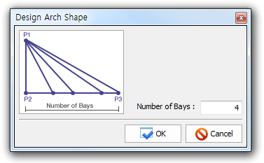
An arch-shaped element set is generated by this function. To activate this function, three points (P1, P2, P3) as shown below must be assigned. The direction of inclined element is changed according to the input order of the points. The number of bays must be inserted.
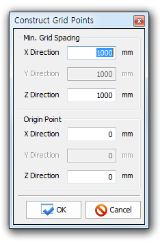
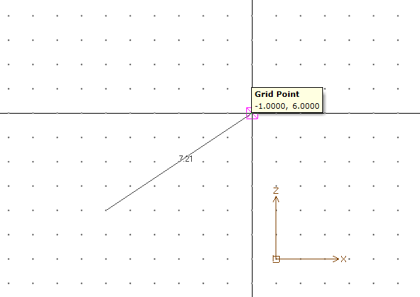
Grid Points...
The numerous points visualizing multiple grid lines as shown below are generated in the Modeling and Result Display Window by this function. The grid lines can be helpful for constructing the geometrical shape of concrete member and the finite element models of plane solid and truss structures. This function is activated by setting the Grid Points to True in the View Options Window. The minimum grid spacing and the coordinates of origin point must be assigned.
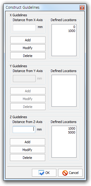
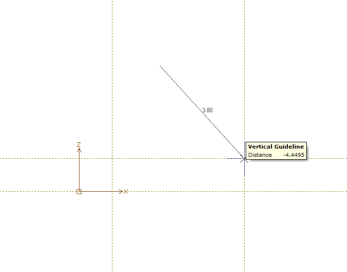
Guidelines...
The guidelines as shown below are generated in the Modeling and Result Display Window by this function. The guidelines can be helpful for constructing the geometrical shape of concrete member and the finite element models of plane solid and truss structures. This function is activated by setting the Guidelines to True in the View Options Window. Horizontal and vertical guidelines are generated by assigning the distances from the orthogonal axes. The guidelines can be added/modified/deleted by changing the assigned distances.
Add Dynamic Guideline
It make easy guideline. User define guideline.
Delete Dynamic Guideline
Create Outer Boundary
The outer boundary of a concrete member is generated by this function. The function is applicable only in the Beginning Mode. It is not activated when the every boundary line shaping a concrete member is not connected completely. The outer boundary is created only once. If another outer boundary is created, the previous outer boundary is deleted.
Create Inner Boundaries
The inner boundaries for modeling the openings of a concrete member are generated by this function. The function is applicable only in the Beginning Mode. It is not activated when the every boundary line shaping an opening is not connected completely. The function must be activated after creating the outer boundary of a concrete member. The openings must be positioned inside of the outer boundary. Multiple inner boundaries can be created.
Create Area
The area of a concrete member surrounded by its outer boundary is generated by this function. This function is applicable only in the Beginning Mode.
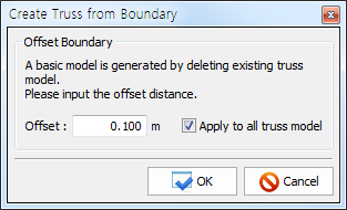
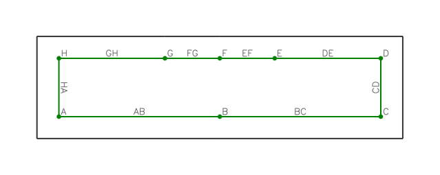
Create Truss From Boundary
Truss elements for a concrete member, with a certain distance away from its outer and inner boundaries, are created automatically by this function. The distance, considered as one-half of the available widths of the truss elements, must be assigned.
Copy Truss To All
A truss model for a given load combination can be copied to those of all load combinations by this function. Caution is needed because the previous truss models for other load combinations are all deleted once the function is activated.
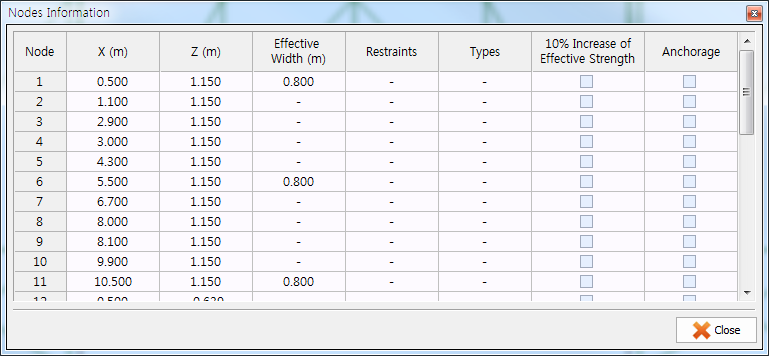
Node Information
The information on the nodes of truss model (strut-tie model) is displayed by this function. The information includes the coordinates of node, width of bearing plate, boundary conditions, node type, and anchorage of reinforcing bars. The information on the coordinates and effective strength of node can be modified by this function.
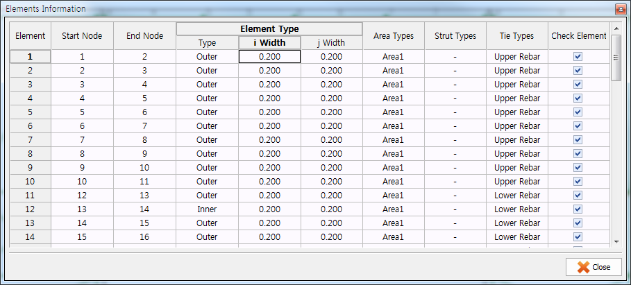
Element Information
The information on the elements of truss model (strut-tie model) is displayed by this function. The information includes the node numbers at element’s both ends (start node, end node), assumed available widths at element’s both ends (i-width, j-width), area type, and tie type. The information on the assumed available widths can be modified by this function.
Renumbering
The element and node numbers (of the finite element models of plane solid and truss structures) that are not in sequential order due to editing of the finite element models are renumbered by this function. The renumbering is activated automatically in the finite element analyses.
Cal. Max Width
The available widths of all elements in a strut-tie model, calculated automatically by the program, are displayed by executing the function DESIGN-Element Information or ASSIGN-Outer Element. The available widths can be modified.